LO1 · Inspection and Testing Requirements
22%of exam
LO2 · Safety Management
3%of exam
LO3 · Inspection Requirements
19%of exam
LO4 · Testing Requirements
56%of exam
LO5 · Practical Only
0%of exam
Quick Facts
- Qualification
- City & Guilds Level 3
- Award reference
- 603/1275/0
- Theory test
- 2391-052
- Theory format
- 60 MCQs · 120 minutes
- Theory conditions
- Open book and invigilated
- Theory pass
- About 75%, subject to adjustment
- Practical assignment
- 2391-502
- Award requirement
- Pass theory and practical
- Guided learning
- 50 hours
- Total qualification time
- 67 hours
- Sitting edition
- Confirm with your centre
Statutory Duties vs Technical Standard
EAWR
- Legal duties in Great Britain
- Controls work and electrical danger
BS 7671
- UK installation technical standard
- Part 6 covers verification
Apply applicable law and technical standard
Document Picker
- New installation→EIC with inspection and test schedules
- New circuit in existing installation→EIC(Apply initial verification to new work)
- Minor work, existing circuit only→MEIWC where suitable(Record the agreed work)
- Replacement consumer unit→EIC(Verify affected circuits)
- Condition of existing installation→EICR with schedules(Agree scope and limitations first)
Test Blueprint
- LO1 requirements
- 13 online questions
- LO2 safety
- 3 online questions
- LO3 inspection
- 11 online questions
- LO4 testing
- 33 online questions
- LO5 performance
- Practical assessment only
- Online test weights
- Published City & Guilds percentages
Book Rules
- 2391-052 references
- BS 7671, On-Site Guide, GN3
- GN3
- Guidance Note 3, Inspection & Testing
- Externally marked tests
- Paper copies only
- Page markers and highlighting
- Permitted within book rules
- Added formulas or procedures
- Prohibited additions
- Reference edition
- Current unless City & Guilds specifies
- Current UK wiring standard
- BS 7671:2018+A4:2026
- A4 assessment alignment
- Check live centre instructions
- Current IET Guidance Note 3
- 10th edition covers Amendment 4
Certificates and Reports
- EIC
- Electrical Installation Certificate
- EIC trigger
- New installation or new circuit
- MEIWC
- Minor Electrical Installation Works Certificate
- MEIWC scope
- Minor work on existing circuits
- Consumer unit replacement
- Use Electrical Installation Certificate
- EICR
- Electrical Installation Condition Report
- EICR purpose
- Suitability for continued service
- Part 6 road map
- Chapters 64 initial, 65 periodic
- Appendix 6
- Model certificates, reports and schedules
Periodic Scope
- Extent
- Parts included in the inspection
- Agreed limitations
- Record exclusions and reasons
- Operational limitations
- Record access constraints and reasons
- Previous records
- Identify changes and compare results
- Sampling
- Agree and record its extent
- Next inspection
- Recommend interval with reasons
- EICR schedules
- Inspections, circuit details, test results
Prove, Test, Prove
Prove the indicator, test dead, prove again
Dead Work vs Live Testing
Dead working
- Isolate and secure all supplies
- Prove dead at work point
Live testing
- Dead working must be unreasonable
- Live working must be reasonable
- Take precautions to prevent injury
Meet all Regulation 14 conditions
Safe Isolation Checks
- Supply source uncertain→Identify and isolate all sources(Include backfeeds)
- Isolation could be reversed→Lock off and retain key(Attach warning notice)
- Before testing for voltage→Prove two-pole indicator(Use suitable proving source)
- Testing for dead→Check relevant conductor pairs(At point of work)
- Voltage detected→Stop and resolve source
- Dead checks complete→Re-prove voltage indicator
- Live work considered→Apply EAWR Regulation 14(All three conditions must hold)
Electrical Safety Duties
- Electricity at Work Regulations
- Statutory duties in Great Britain
- BS 7671
- Technical standard for electrical installations
- EAWR Regulation 12
- Isolation and cutting off supply
- EAWR Regulation 13
- Prevent accidental re-energisation during work
- EAWR Regulation 14
- Three conditions for live work
- EAWR Regulation 16
- Competence or appropriate supervision
- GS38
- Low-voltage test equipment guidance
- Before testing
- Assess risks and plan controls
- Electrical safety law in NI
- Electricity at Work Regulations 1991
Safe Isolation
- Isolation point
- Identify equipment and every supply
- Lockout
- Secure isolation and retain key
- Warning notice
- Identify isolated equipment
- Prove dead
- Suitable two-pole voltage indicator
- Before and after proving dead
- Check indicator on proving unit
- Voltage present
- Stop and resolve supply source
- Alternative supplies
- Check PV, batteries, UPS, generators
- Non-contact voltage pen
- Preliminary indication only
EICR Code Memory
Danger, potential danger, improvement, investigate
Initial vs Periodic
Initial verification
- New work before service
- Correct and retest defects
- Issue EIC or appropriate MEIWC
Periodic inspection
- Assess continued suitability
- Report within extent and limitations
- Code observations on EICR
Purpose determines certificate or report
EICR Code Picker
- Immediate danger present→C1(Make safe where practicable)
- Potentially dangerous defect→C2(Urgent remedial action)
- Safety improvement advisable→C3(Advisory under A4)
- Potential issue cannot be verified→FI when further investigation justified(Advisory under A4)
- Area excluded by agreed scope→Record limitation and reason(FI needs an identified issue)
- One or more C1/C2 codes→Report unsatisfactory
Visual Inspection
- Initial inspection
- Before energising the installation
- Equipment selection
- Check suitability for external influences
- Equipment condition
- Look for damage or deterioration
- Basic protection
- Check barriers and enclosures
- Fault protection
- Check earthing and protective bonding
- Circuit protection
- Check protective device type and rating
- Conductor identification
- Check line, neutral and earth
- Isolation and switching
- Check provision, access and labels
- IP first numeral
- Access and solid-object protection
- IP second numeral
- Water ingress protection
- Sensory evidence
- Use sight, sound, smell safely
C2 vs FI Under A4
C2
- Potential danger can be identified
- Urgent remedial action
- Overall outcome unsatisfactory
FI
- Issue cannot be fully verified
- Further investigation advised
- Outcome unchanged by FI alone
Classify established risk when possible
EICR Observations
- C1
- Danger present, act immediately
- C2
- Potentially dangerous, urgent remedial action
- C3
- Safety improvement recommended
- FI under Amendment 4
- Further investigation is advised
- A4 unsatisfactory outcome
- Any C1 or C2
- A4 C3 or FI alone
- Advisory, outcome unaffected
- Known safety defect
- Classify the observed risk
- A4 recipient guidance
- Include guidance based on Appendix 6
- N/A on inspection schedule
- Item does not apply
- LIM on inspection schedule
- Documented inspection limitation
- FI wording in A2:2022
- Further investigation without delay
Ring Test Trio
Ends first, then line-neutral, then line-earth
Ze vs Zs
Ze
- External loop impedance
- Supply-side contribution
Zs
- Whole earth fault loop
- Includes circuit contribution
Use Zs for circuit disconnection
Test Selection
- Verify CPC path→Low-resistance continuity test
- Verify ring connections→Three-stage ring test
- Find insulation weakness→Insulation resistance test(Choose voltage from Table 64)
- SPD cannot reasonably be disconnected→250 V DC insulation test(Minimum 1 MΩ)
- Confirm correct switching conductor→Polarity test
- Check electrode resistance→Earth electrode resistance test(Use method suited to site)
- Verify overcurrent fault disconnection→Determine Zs(Compare applicable device limit)
- Check device breaking capacity→Determine prospective fault current
- Verify RCD operation→AC trip test at IΔn(Compare device time criterion)
- Verify multiphase conductor order→Check phase sequence
- Check voltage at load→Assess voltage drop(Use measured conductor resistance)
Test Order
- Initial verification
- Follow applicable test sequence
- Dead tests
- Before tests requiring energisation
- Early dead tests
- Continuity, insulation resistance, polarity
- Earth electrode where present
- Measure before initial energisation
- Initial test failure
- Correct defect, repeat affected tests
- Periodic testing
- Adapt tests to condition and scope
- Continuity instrument
- Low-resistance ohmmeter
- Instrument accuracy
- Calibration plus ongoing accuracy checks
- GS38 leads and probes
- Check condition and suitability
Ring vs Radial Continuity
Ring final
- Three end-to-end readings first
- Then two cross-connected stages
Radial
- Verify CPC continuity to points
- Use R1 + R2 or R2
Match continuity method to topology
Protective and Ring Continuity
- CPC
- Circuit protective conductor
- R1 + R2
- Line plus CPC path resistance
- R2 continuity method
- CPC resistance using wander lead
- Protective bonding continuity
- Measure and record resistance
- Ring step 1
- End-to-end r1, rn and r2
- Ring step 2
- Cross-connect opposite line and neutral
- Ring step 3
- Cross-connect opposite line and CPC
- Ring step 3 midpoint
- Approx. (r1 + r2) ÷ 4
- Ring schedule value
- Highest measured step 3 result
- Unequal line and CPC sizes
- Step 3 readings may vary
- Parallel paths
- Can mask discontinuity
- Test lead resistance
- Null or subtract before interpreting
Loop Impedance vs RCD Operation
Zs check
- Verifies earth fault loop impedance
- Compare applicable device criterion
RCD trip test
- Inject rated residual test current
- Time device operation
Select checks for protective measure
Insulation Resistance
- Insulation resistance result
- Record resistance in MΩ
- 230 V circuit standard test
- 500 V DC, minimum 1 MΩ
- SELV or PELV
- 250 V DC, minimum 0.5 MΩ
- Sensitive equipment or SPD
- Disconnect to prevent damage/interference
- Disconnecting SPD impracticable
- 250 V DC, minimum 1 MΩ
- Electrical separation
- Verify isolation from other circuits
- SELV separation
- Verify separation from Earth too
- Low reading
- Investigate affected circuit or equipment
- SPD
- Surge protective device
Earthing and Fault Current
- Ze
- External earth fault loop impedance
- Zs
- Total earth fault loop impedance
- Calculated Zs
- Ze + (R1 + R2)
- Measured Zs screening
- 0.8 × tabulated maximum
- Close to screening limit
- Check detailed temperature correction
- TT with RCD fault protection
- RA × IΔn ≤ 50 V
- RA in TT calculation
- Electrode and protective conductor resistance
- PSCC
- Prospective short-circuit current
- PEFC
- Prospective earth fault current
- PFC
- Maximum prospective current at point
- Breaking capacity
- Check against prospective fault current
- Earth electrode resistance
- Fall-of-potential test where suitable
RCDs and Functional Checks
- RCD verification
- AC test at rated IΔn
- General non-delay RCD
- Up to 300 ms
- Type S time-delayed RCD
- 130–500 ms
- Type S time delay
- Fault protection, where appropriate
- Half-current or five-times tests
- Optional diagnostic tests
- Dead polarity
- Verify switching in line conductor
- Supply polarity
- Confirm at the origin
- Phase sequence
- Check order is maintained
- Functional testing
- Confirm equipment operates as intended
- Voltage drop
- Use measured conductor resistance method
- Resistive single-phase estimate
- Design current × line-neutral resistance
- IΔn
- Rated residual operating current
Practical Handover
Inspect, test, interpret, document
Task A vs Task B
Task A
- 30-minute visual inspection
- Books closed
Task B
- 150-minute practical
- Books for confirming results only
Task C is separately timed
Practical Tasks
- 502 Task A
- Visual inspection, 30 minutes
- Task A references
- Closed book
- 502 Task B
- Practical, 150 minutes
- Task B references
- Only for confirming test results
- 502 Task C
- Short-answer paper, 80 minutes
- Task C references
- BS 7671, On-Site Guide, GN3
- Task B permitted books
- BS 7671, On-Site Guide, GN3
Practical Records
- Initial work
- Verify compliance and certify
- Periodic work
- Classify observations and report
- Schedule entries
- Record results against matching circuits
- Sign-off
- Use appropriate declarations and signatures
- EICR handover
- Include schedules and recipient guidance
- Instrument records
- Identify instruments used
- Practical test evidence
- Compare readings with applicable criteria
Common Traps
Combined Award
2391-052 theory test ≠ 2391-502 practical assignment
Reference Books
Books for confirming Task B results ≠ Permission to consult testing procedures
Proving Dead
Voltage pen indicates possible voltage ≠ Two-pole test proves dead
Initial Certification
Adding a new circuit ≠ Minor works certificate
Periodic Limitations
Agreed inaccessible area ≠ Automatic FI observation
Amendment 4 Outcome
FI alone ≠ Unsatisfactory EICR outcome
Insulation Test Voltage
250 V for connected SPD exception ≠ 0.5 MΩ SELV/PELV minimum
Ring Readings
Lowercase ring end-to-end readings ≠ Recorded uppercase R1 + R2
Loop Impedance
80% ambient screening figure ≠ Universal maximum permitted Zs
RCD Verification
Built-in RCD test button ≠ Instrumented RCD trip-time test
Protective Device Checks
Maximum earth fault loop impedance ≠ Minimum adequate device breaking capacity
Last Minute
- 1.Confirm assessment edition with your centre
- 2.Pass both 2391-052 and 2391-502
- 3.Testing has 33 online questions
- 4.Lock off every supply source
- 5.Prove voltage indicator before and after
- 6.Complete relevant dead tests before energising
- 7.Record three ring end-to-end values
- 8.Select insulation voltage from Table 64
- 9.Compare Zs with device-specific limit
- 10.Test RCD trip time at IΔn
- 11.Use EIC for new circuits
- 12.Agree and record EICR limitations
- 13.A4 C1/C2 make EICRs unsatisfactory
- 14.A4 C3/FI are advisory
- 15.Attach inspection and test schedules
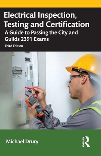
 Buy on Amazon
Explore More City & Guilds UK Trade Qualifications
Continue into nearby exams from the same family. Each card keeps practice questions, study guides, flashcards, videos, and articles in one place.
More From This Family
Videos and articles for deeper review.